How to work with Visual Lighting Interface
Electrical discipline comes with an interface to the lighting design package Visual Pro. The interface enables the export of room dimensions to Visual Pro and also re-imports calculated lighting fixture arrangements and lighting fixtures properties such as: name, load information, exact 2D and 3D dimensions back to Electrical discipline into the floorplan.
-
Select
 ( Visualization) tool.
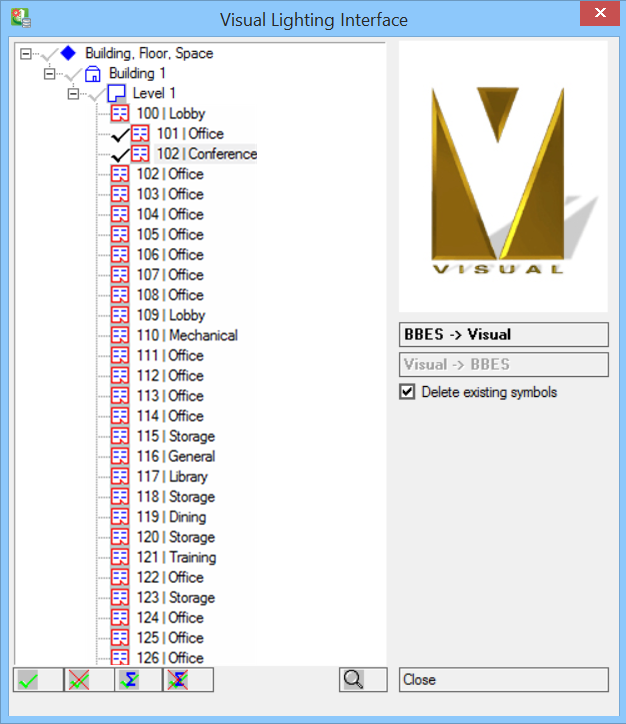
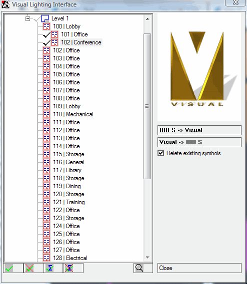
Opens the Visual Lighting Interface dialog.
It is now necessary to select at least one room in the rooms list. Selection enables BBES->Visual.
( Visualization) tool.
Opens the Visual Lighting Interface dialog.
It is now necessary to select at least one room in the rooms list. Selection enables BBES->Visual.
-
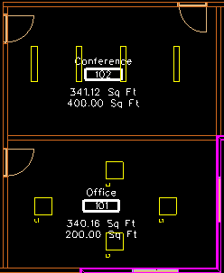
Click on
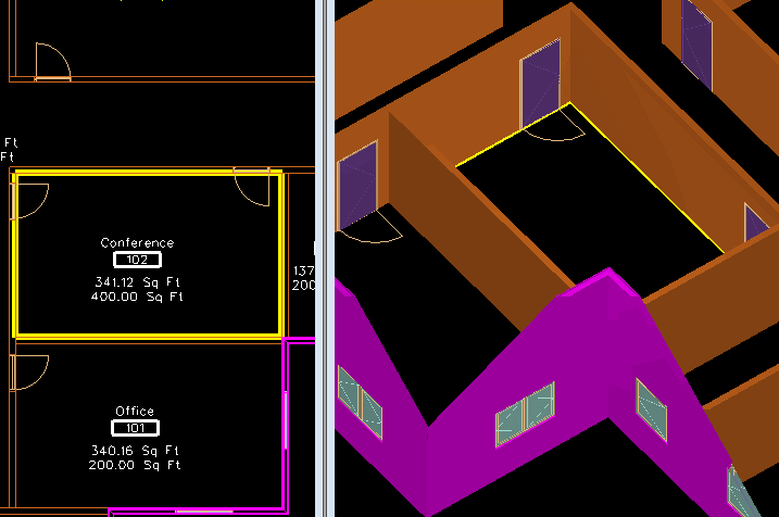
 to visualise the selected room in the drawing.
To return to the Visual Lighting Interface, simply click in the drawing view.
to visualise the selected room in the drawing.
To return to the Visual Lighting Interface, simply click in the drawing view.
-
Next, click BBES->Visual.
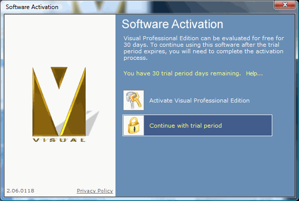
Visual application interface opens.
If you use the trial Version, click "Continue with trial period".
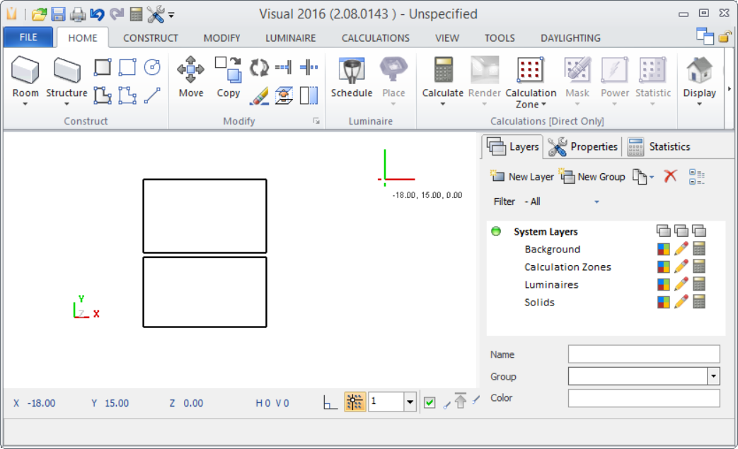
Visual Pro run in the background and the room dimensions, including width, length and height are transferred.
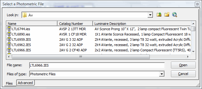
- First you need to select a lighting fixture. Click menu option. Opens the Photometric File selection dialog.
- Click in Look in field and navigate the path and select a manufacturer, for example Lithonia, Typ Fluorescent, Av. Select one of the types listed, e.g. LTL8192.IES.
- Select the Luminaire schedule in the list and click OK to accept this lighting fixture for the lighting calculation. Place Luminaire with one of the functions menu. Now you can calculate the room.
-
Next, ensure that the Visual file is Exported. Use the option to export.
Note: It is required to Export the Visual Pro file for Visual interface to work in Electrical discipline.The Visual->BBES is enabled.
-
Click Visual->BBES.
Opens the Lighting Calculation Symbol Matchtable dialog.
The match-table creates a connection for the lighting fixture that is imported from Visual Pro into the Electrical drawing and a lighting fixture symbol. This only needs to be done the first time a new lighting fixture type is imported, Electrical discipline stores this link information (this link can be changed at any later date). The Symbol Matchtable also offers the following options:The red "X" placeholder symbol indicates that there is no match/link for this luminaire available yet.
- Import 2D dimensions: imports lighting fixture symbol 2D dimensions from manufacturer database
- Import 3D dimensions: imports lighting fixture symbol 3D dimensions from manufacturer database
- Import load: Imports lighting fixture load information from manufacturer database
- Update subtype: imports lighting data from manufacturer database
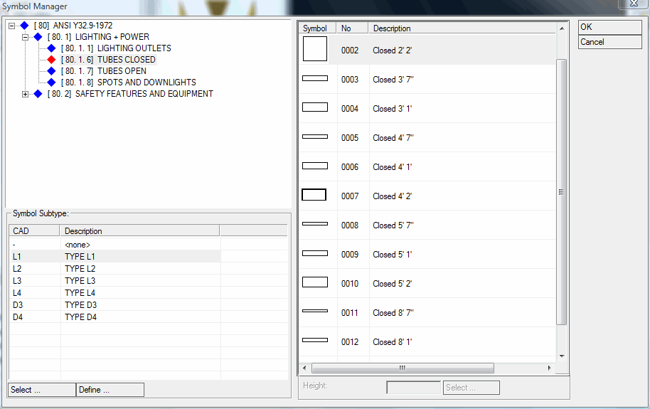
- Click Symbol. Opens the Symbol Manager dialog.
- Select the Closed 2' 2" symbol in the TUBES CLOSED section and, for example, Subtype L1, and click OK. The Visual lighting fixture is now linked to a lighting fixture symbol. You will see the symbols in place of red "X" placeholder in the Symbol Matchtable.
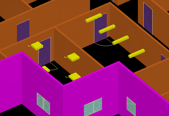
- Click OK in Symbol Matchtable dialog. The lighting fixture arrangements are now inserted into the drawing.
-
Select
 (Modify Symbol Load) tool.
Opens the Object Properties dialog with the Individual Load information.
This load information was handed down from the manufacturer database, then through the Visual Pro interface into the Electrical discipline drawing/environment.
The computed lighting results can be best reviewed in Luminaries schedule.
(Modify Symbol Load) tool.
Opens the Object Properties dialog with the Individual Load information.
This load information was handed down from the manufacturer database, then through the Visual Pro interface into the Electrical discipline drawing/environment.
The computed lighting results can be best reviewed in Luminaries schedule.
-
Select
 (Output Manager) tool.
The Output Manager dialog opens.
(Output Manager) tool.
The Output Manager dialog opens.
-
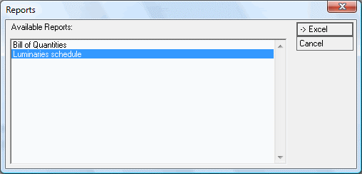
Select Bill of Quantities report option.
In the Reports options list select Luminaries schedule and click -> Excel to create an Excel schedule.
Luminaire schedule lists Symbol, Type, Description, Total Power and Manufacturer including Catalog number.